Advanced Technology Solar Telescope (ATST)
|
Advanced Technology Solar Telescope (ATST) |
|
There are a variety of lens, but essentially they are
|
 |
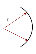
| The most important quantity for a lens is the focal length f: i.e. how far from the lens do parallel rays get focussed. |  |
\color{red}{
\frac{1}{f} = \left( {n - 1} \right)\left( {\frac{1}{{R_1 }} + \frac{1}{{R_2 }}} \right)}
|
 |
\color{red}{
f = \frac{R}{2}}
because if you place a source at the centre the light must be reflected back there.
\color{red}{
\frac{1}{f} = \frac{1}{R} + \frac{1}{R}}
|
 |
| Image is real and inverted | 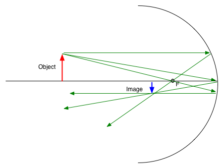 |
is this interference experiment done for light.
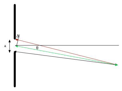
| Distance between sources is small (d) Distance to detector is large (D) so waves can be treated as plane waves, giving constructive interference |  |
| If we have an extra ½ λ, will get destructive interference. |  |
\color{red}{\theta = \frac{{n\lambda }}{d}}
| For water waves, this can be done by two sources. For light, there is an extra problem: sources don't stay in phase... |  |
Geometry:
| \color{red}{\lambda = d\sin \left( \theta \right)} (note small angle approx can't be used here) so if white light is incident on diff. grating, it will be split up into constituent wavelengths |  |
| To have destructive interference between light from centre and edges, need
\color{red}{
D_1 - D_2 = \frac{\lambda }{2}}
difference in paths
|
 |
| Done properly: need Huyghens principle Field is
\color{red}{
dE = \frac{{E_L }}{r}e^{i\left( {kr - \omega t} \right)} ds}
|
 |
| The intensity falls of very rapidly away from the centre line. |
| Means that a point will be spread out into a disk, and hence the image of two close objects will overlap | 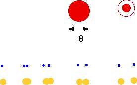
|
| if the light from the bottom level travels λ/2 further, there will be destructive interference between the two reflections. Since the path will depend on the separation, there will be a pattern of lines |  |
| We can use this constructively to reduce the reflection from lenses: e.g. a surface will reflect
\color{red}{
I_R = \frac{{n^2 - 1}}{{n^2 + 1}}I_0 }
|
 |
| By coating the lens, we can arrange for destructive interference in the reflected wave |  |  |
| Glass has (slightly) different refractive indices n for different λ, Hence a prism can be used to produce a spectrum. |  |
| Effect is blurred image |  |
| One solution is to eliminate light from outside of lens by stopping down | 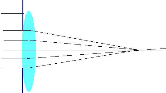 |
| Unfortunately this reduces the area, so you get less light. Only real way out is to go to non-spherical lenses/mirrors. e.g. for a telescope, spherical mirror gives blurred image | 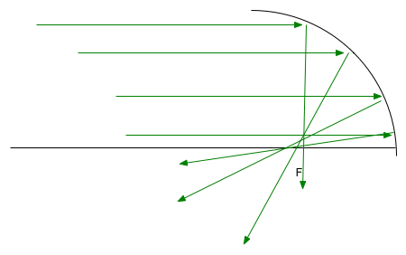 |
| Can be corrected by going to a parabolic mirror (but this only works for objects at infinity) | 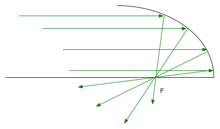 |
Chromatic aberration:
| Glass disperses light into constituent wavelengths, so get different foci for different wavelengths | 
|
|
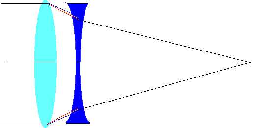
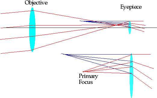
Simplest is two lens refractor. Objective is large
lens at "front", brings light to a primary focus.
Eyepiece is used to magnify image. Magnification: if f₀ is focal length of objective f₁ is focal length of objective
\color{red}{
M = \frac{{f_o }}{{f_e }}}
| 
|
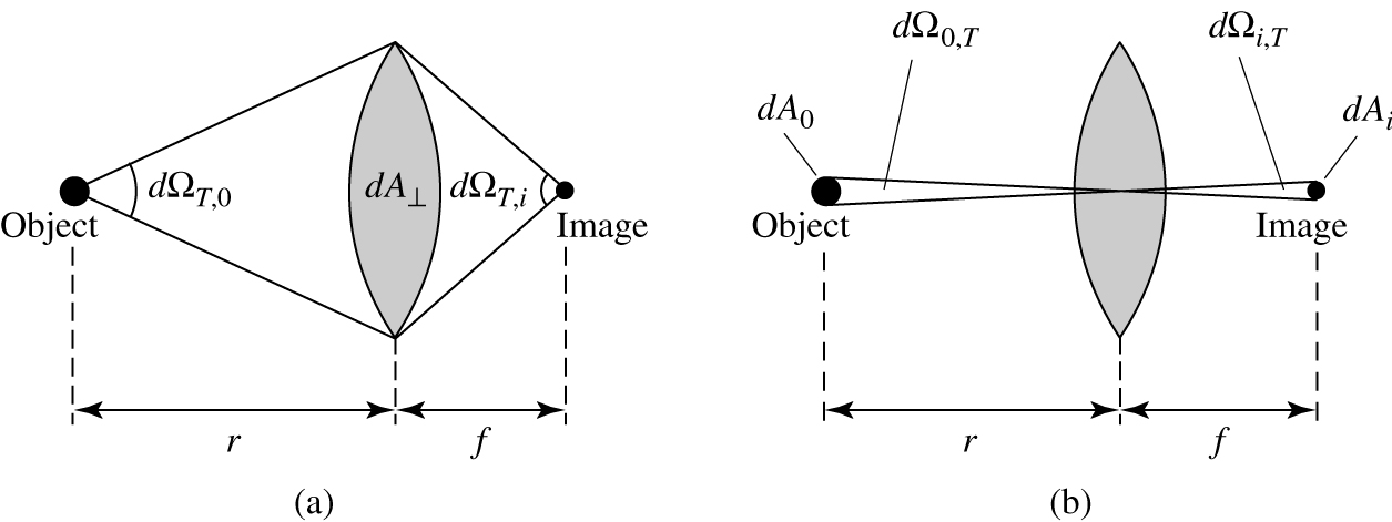
| But also want image to show maximum image intensity Ii: If we have a finite sized object, then (Height) area of image will be ∝ (f) f2. Hence "figure of merit" in comparing two telescopes will be focal ratio
\color{red}{
F = \frac{f}{D}}
Want this to be as small as possible: good camera lens will have F ~ 2.
Illumination
\color{red}{
J \propto \frac{1}{{F^2 }}}
|
 |
|
Newtonian reflectors Replace objective lens by mirror: Advantages:
| 
|
| Disadvantage: Spherical Aberration remains | 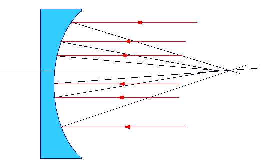
|
| An Extraordinary Spiral from LL Pegasi | 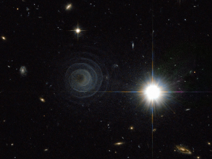 |
Credit: ESA, Hubble, R. Sahai (JPL), NASA
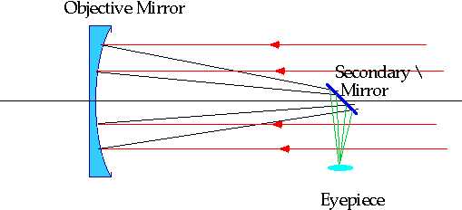
| "Best" standard telescope is Schmidt- Cassegrain Corrector plate is very weak aspherical lens to exactly (well, almost) compensate for spherical abberation | 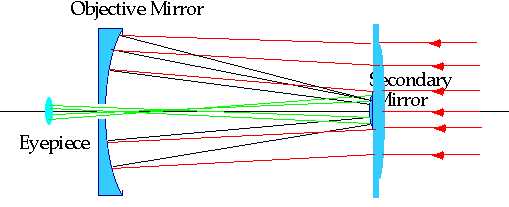
|
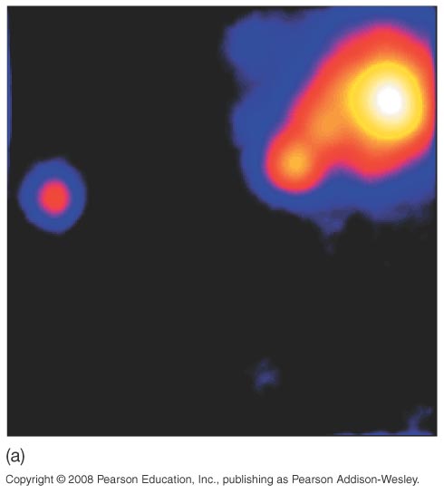
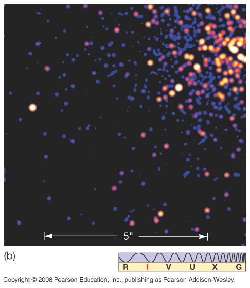
| A spectacular picture from the Hubble: large masses can bend light, | 
|
| so a very large cluster of galaxies (about 1013 MSun) can act as a (lousy!) lens. This cluster is producing multiple images of a much more distant galaxy. |  |
| Adjust position of pads several times per second to keep 'artificial star' aligned | 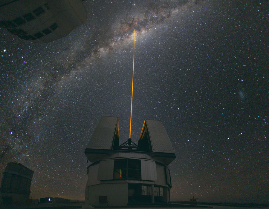 |
| λ | E | Detection: | Absorption: | Observatories | Production: | ||
| ∼ 1cm ↔ 100 km | Radio-receivers (masers for highest sensitivity) | Longer waves absorbed by atmosphere | Sea-level | Sun, Jupiter, few stars, pulsars, cold hydrogen (21cm), galactic nuclei | |||
| Need lots of collecting area but also high resolution ⇒ Large dishes (Arecibo), many hooked together (VLA) |

A Very Large Array of Radio Telescopes Credit: NRAO, NSF |
||||||
| λ | E | Detection: | Absorption: | Observatories | Production: |
| ∼ 10-6m ↔ 10-1m | Radiometers, Photoconductors | All except shortest absorbed by atmosphere | mountain top, since H20 is worst offender | Sun, stars, galactic gas |
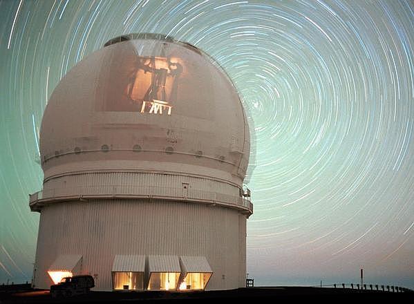
| Canada-France-Hawaii Telscope (on Mauna Kea) |
|
| λ | E | Detection: | Absorption: | Observatories | Production: |
| ∼ 400 nm ↔ 800 nm | ∼ 2 eV | Eye, photograhic film, photoelectric detectors | Clouds | Sea level | Everything except cold matter |
| High, dry observatories (to avoid twinkle) |

The VLT Interferometric Array Credit & Copyright: European Southern Observatory |
||||
| λ | E | Detection: | Observatories | Absorption: | Production: |
| ∼ 0.1 nm ↔ 400 nm | ∼ 1keV ↔ 3eV | Photograhic film,photoelectric detectors | High for λ < 10-7 m | satellites or mountain top observatories | Hot stars, hot gas |
| λ | E | Detection: | Absorption: | Observatories | Production: |
| ∼ 10-12 m↔10-10 m | ∼ 1 MeV ↔1 keV | Photograhic film, photoelectric detectors, photomultpliers | High | satellite | Highly excited atoms: T > 105 K |
| must get above atmosphere (Einstein, Chandra, XMM satellites) |

XMM Launched Drawing Credit: D. Ducros, XMM Team, ESA |
||||
| Can't be focussed or reflected: need to use grazing incidence mirrors |  |
| λ | E | Detection: | Absorption: | Observatories | Production: | |
| < 10-12 m | ∼ 1 MeV ↔1018eV | Spark chambers, Cherenkov radiation in atmosphere | High | Satellite or upper atmosphere | Compact objects (e.g. black holes, neutron stars, supernovae) | |
| can use the atmosphere as a detector |

HESS Gamma-Ray Telescope Credit: The HESS Collaboration |
|||||
| and above all, the Hubble which sees in the UV and IR and is above everything! |

The Orbiting Hubble Space Telscope Credit: STS-103, STScI, ESA, NASA |
These give us 70 octaves!
What does the whole sky look like: see Chromoscope| 25.2m 7 segment primary mirror | 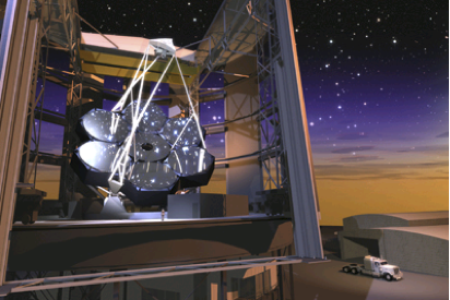 |
| $0.8B, operational 2017, Ritchey-Chretien design | 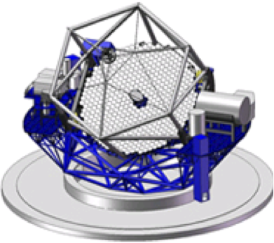 |
| ~42m primary mirror, consisting of 906 x 1.4 segments, adaptive optical control | 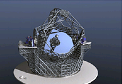 |
| L2 is preferred place: min of PE | 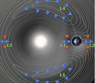 |
| Full range of space observatories | 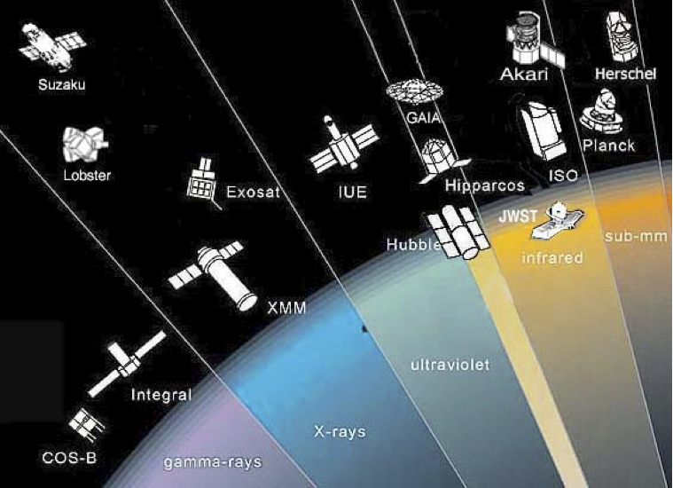 |
| 6m primary (Hubble was 2.8m) | 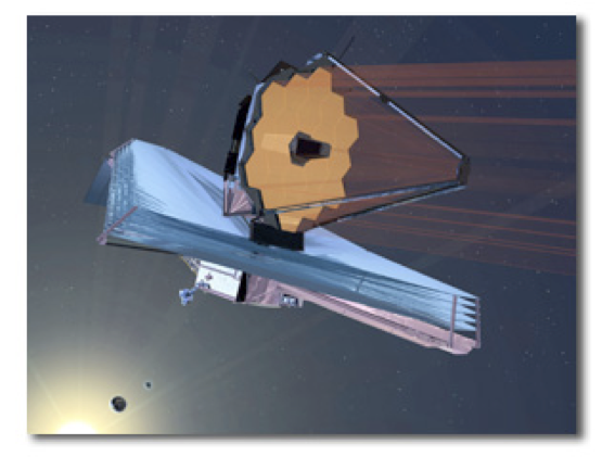 |