\color{red}{B_I }
is in opp. direction to \color{red}{\delta B_A }
Lenz's law follows from energy conservation: if the induced field was in the
same direction as the applied field, it would induce a larger current which would
produce a larger field which....
The field through it changes by 1000 Gauss. What is the change in flux?
3 Wb
30000 Wb
3x10⁻⁴ Wb
30 Wb
e.g. A loop of wire has resistance 5Ω,
area 30cm2.
The flux through it changes by 3x10⁻⁴ Wb in .05 seconds. What is the induced
EMF?
6 V
6x10⁻³V
6000 V
.06 V
A loop of wire has resistance 5Ω,
area 30cm². The flux through it changes by .0003 Wb in .05 seconds, giving an induced EMF of 6x10⁻³ V. What is the current?
1.2 A
1.2x10⁻³ A
1.2x10⁻⁶ A
12001 A
Generators
Coil of wire with many turns is spun in mag. field (Yes: this looks like a
motor. In fact simple motors and simple generators are the same).
A simulation
For N turns, in any positions:
φ= NBAcos (θ)
If θ = ωt
then
φ = NBAcos (ωt)
so
ξ = NBA ωsin(ωt)
This gives us alternating current (AC): the direction of the current keeps changing
e.g suppose we have a coil of 1000 turns with area of 50 cm² revolving in a magnetic field B.
How large would the field need to be to produce 110 V at 60 Hz?
.37 T
.06 T
.37 Wb
.06 Wb
Eddy Currents
Induced currents in large volumes of conductor which produce heating
If field out of surface increases, current will flow, producing heat by resistance.
Partially overcome by laminating metal,
so each current must have a smaller E.M.F., so the power loss is much less
A useful application is Electromagnetic Braking
Wheel rotating inside mag. field will have current induced in it, induced mag. field will interact with external field to slow down wheel, so rotational K.E. converted to heat, but no friction to cause wear.
Faraday expt. shows that changing current (and hence flux) in one circuit will
produce a changing E.M.F. in second.
If a circuit can affect a second one, it
can affect itself:
quantifying this gives coef. of self-induction or inductance
of a coil.
Coefficient of self inductance L defined by
φ = LI
Ɛ  = - δφ = -LδI
       δt     δt
e.g. For a long solenoid, length l, x-sect A:
the flux through any one loop due
to itself and all the others is
δφ = BA = μ₀ N I A
               l
Total flux is just
φ = Nδφ  so  L = μ₀ N²A
                      l
Note: in most practical cases we cannot calculate L but it can always be measured.
Unit of L is "Henry"
L ~ μ₀(length)
Proportional to the square of the no. of turns:
How big is this in practice?
A solenoid consists of 1000 turns, 50 cm, x-sect 40 cm²: what is the self-inductance?
.01 H
1 H
100 µH
1 mH
Energy stored in an Inductance:
Energy must be supplied to increase the current: if there is no resistance,
an inductance can be used to store energy
U = ½ L I²
how much energy is stored in practice?
A solenoid consists of 1000 turns, 50 cm, x-sect 40 cm², so it has a self inductance of 10 mH. If there is a current of 30 A in it, how much energy is stored
4.5 J
4.5x10³ J
4.5x10⁻² J
4.5x10⁻⁶ J
It is useful to talk about energy density, as we did for a capacitor.
For a solenoid,
\color{red}{B = \mu _0 \frac{{NI}}{\ell }}
and \color{red}{L = \mu _0 \frac{{N^2 A}}{\ell }}
so we can write
\color{red}{
U = \frac{{B^2 }}{{2\mu _0 }}\ell A}
or energy/unit volume as
\color{red}{
u = \frac{U}{V} = \frac{{B^2 }}{{2\mu _0 }}}
How big a magnetic field would be needed to store the same amount of energy as gasoline (~1010 J m-3)
160 G?
160 T?
2.5x10⁴ T
2.5x10⁴ G
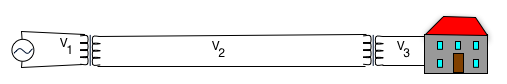
Transformers
Power loss in transmission is ~ RI²: hence can reduce current by
increasing voltage.
e.g suppose we want to transmit power P₀ = 1 MW over 500 km with a wire of resistance of 10-8Ω/m,
what is power loss PL at 110 V
what is power loss PL at 1 MV
However, voltage must be decreased locally: only works for A.C.
Important for power transmission
Means that generator will produce power at about 1kV, stepped up to 1MV, stepped down to 120V (usually in several stages)
assume no load: then voltage across prim.
V₁ = N₁ dφ , V₂ = -N₂ dφ  = - V₁ N₂
       dt            dt       N₁
Also flux through, prim. and sec. must be same:
N₁I₁ = N₂I₂
Hence Power
I₁V₁ = I₂V2 = V₂²/R₂
if resistance R₂ is connected across secondary.
This is "step-down" V₂ < V₁ and so I₂ > I₁.
Inductances in a circuit:
What happens if the switch is closed?
A current will start to flow,
but this will produce a flux in the solenoid,
which will produce an EMF in the opposite direction,
which will reduce the current...
Kirchoff's loop law gives
EMF from Battery + EMF from Inductance - RI = 0 or
- L dI + V - I R  = 0
    dt
which is very like the equation we had for a capacitance
note we usually pretend that an inductance has no resistance
This is a current which increases from zero to the Ohm's law value I = V/R.
e.g if our circuit has a battery with an EMF of 12 V, R = 10 Ω and L = 2mH,
What will the final current be?
How long will the current take to increase to 90% of its final value?
A. C. in Circuits
For various reasons, most practical ( Household) circuits use Alternating Current (A.C.): Supply voltage V = Vm sin(ωt).
Usually talk about "root mean square" (r.m.s.) value of voltage.
so average \color{red}{P_{rms} = \frac{{V_m ^2 }}{{2R}}\left\langle {1 - \cos \left( {2\omega t} \right)} \right\rangle = \frac{{V_m ^2 }}{{2R}}}
e.g. household supply of 120 V is applied to a 100 W lamp.
What is Vm?
What is Im?
What is R?
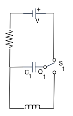
Capacitors and Inductors and AC
What happens if we have a capacitor and inductance in a circuit? When the switch is thrown, current will start flowing, but cannot flow through cap. so it just gets charged up
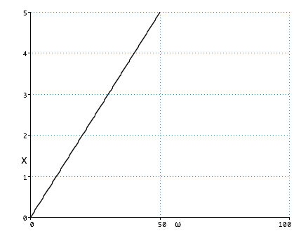
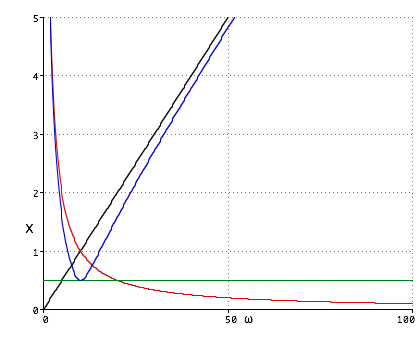
XL is the "impedance" of the inductor. Note that it increases as ω increases: this means that an inductor behaves like a small resistance at low frequency and a large one at high frequency.
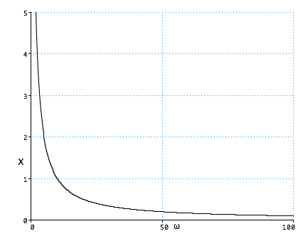
Similar calculation for a capacitance:
If the charge is \color{red}{Q = Q_0 \cos \left( {\omega t} \right)}
and voltage is \color{red}{V_C = \frac{Q}{C}}
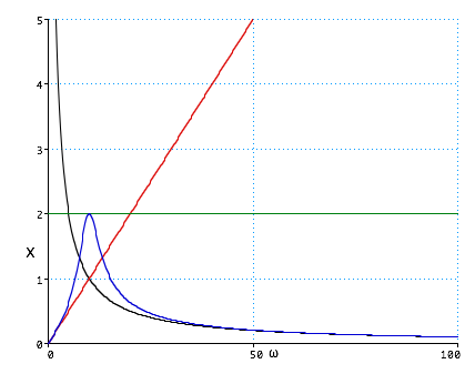
so the impedance of the capacitor decreases as ω increases: this means that it behaves like a large resistance at low frequency and a small one at high frequency.
The combined effect is to give a circuit with a big impedance at both small and large ω, but there is some value where the two cancel each other out, at
\color{red}{
\omega L = \frac{1}{{\omega C}}}
(Quite complicated to prove). Current in this circuit looks like