PHYS 1008 Electric Circuits
 www.ibiblio.org/ pub/Linux/apps/circuits/
| By the end of this you should be able to do the following
- Understand what current means at both a microscopic and macroscopic level
- Use Ohm's law.
- Find the resistance of a material
- Understand nerves in a qualitative way
- Interpret circuit diagrams
- Solve simple circuits
- Understand Kirchoff's laws
- Solve (easy!) complex circuits
- how capacitors work in circuits
|
Resistivity
Some materials allow charges to move around: these are conductors.
Current: the rate at which charge moves through a wire (C s-1), but
this is so important that it gets its own name
1 Ampere = 1 Amp = 1 C s-1.
It is very useful to think of current as the flow of a liquid:(remember our
earlier analogies). We can think of wire consisting of a large number of charges, which all flow
with the same speed.
If there are
- n positive charges/unit volume
- charge q on each
- velocity v
- in a wire with X-sect area A
|
 |
|
Note (very important!) you cannot distinguish a positive charge moving in one direction with a negative charge moving in the other: qv is a constant.
|
 |
| or even a mixture |
 |
Unfortunately Franklin guessed wrong: he assumed that current consists of +ve
charges, whereas it (in most metals) consists of electrons. However, currents
can occur in many forms: e.g.
- Electrons in wire
- Electrons in vacuum
- Protons in an accelerator
- Electrons and holes in a semiconductor
- +ve and -ve ions in (e.g.) a salt
so maybe Franklin wasn't so wrong after all! There are ways to tell what is
actually flowing.
We have used q as a generic charge: from now on we will use
q = e = -1.6 x 10⁻¹⁹ C.
The average velocity is called the "drift velocity". How fast would
you expect electrons to move?
Why is this so small? We just found the drift velocity for an electron to be about 1mm/s. Surely
this is much too small: when you throw a switch the light goes on immediately?
So:
- The calculation is wrong: in fact the electrons move almost at the speed
of light.
- The wire is "full" of electrons. When the switch is turned on,
all the electrons will move simultaneously
- The drift velocity is only an average, and some move much faster, which
is why a light takes time to "warm up"
- We have a huge random velocity of electrons and a very small directed velocity (note: wind velocity has very little to do with the velocity of the air molecules!)
Resistance
| What makes a current flow? Only thing that can move charges is an electric field.The wire acts as a "pipe" for the electrons to move in. If there
is a field inside a wire, this means there must be a potential difference (or
"voltage") along the wire. |
 |
- **** But you said that a conductor was an equipotential:
how can it have a potential difference along it?
That was electrostatics: i.e.
all currents had finished flowing. Also: we treated lines of force as more or
less fixed in space. However in a wire they are parallel to the surface of the
wire, so as you bend the wire, the direction of the lines changes.
Ohm's law relates the Current, Resistance and Voltage
V = I R
| Actually, this is always true, by definition: what makes it useful is that
for most metals, the resistance R is a constant. Metals conduct equally well in all directions: the resistance is just 1/slope of curve (why?). A diode is a device designed to conduct current in one direction only. |
 |
Units: if I is measured in amps, V in volts then R is in ohms Ω
Expect resistance to depend on shape of conductor, R
- ∝ length of conductor
- ∝1/area
ρ has the largest range of values for any physical constant.
| Conductors |
Ag |
1.47x10⁻⁸ |
| |
Cu |
1.72x10⁻⁸
|
| |
C (as graphite) |
3.5x10⁻⁸ |
| Semiconductors |
Si |
2300 |
| |
Ge |
0.6 |
| Insulators |
C (as diamond) |
1015 |
| |
Quartz |
7.5x10¹⁶ |
| |
Glass |
1010-1014 |
Note that ρ depends on crystal structure of material
e.g. 12-gauge household wiring has an X-section of ~ 10-6 m2. What is the resistance of a 1000 m length?
ρCu ≈ 1.7x10⁻⁸Ωm)
- 17 Ω?
- 1.7x10⁻⁶ Ω?
- 1.7x10⁶ Ω?
- 0 Ω?
Nerve Conduction
| Signals are transmitted in mammals by nerve fibres. called axons. Most nerve fibres are "myelinated": surrounded by myelin sheath which acts as (poor) insulator. |
 |
Mechanism is very different from normal conduction:
- pulses travel very slowly (~ 10ms-1)
- resistance is extremely high ρ ~ 2Ω m (Cu has ρ ~ 10-8Ω m)
- large capacitance
- insulation is poor:
- myelinated nerves have Rm ~ 40Ω m²
- non-myelinated nerves have Rm ~ 0.2Ω m²
- immersed in conducting fluid
- one-way conduction only
- either transmits or not:
Diffusion tells us that concentrations should equalise: e.g. Na+ is much more concentrated outside cell, so diffusion should be inwards and K+ should flow outwards
- Concentrations are in moles m-3. However there is also a + charge on the outside, giving a "resting" potential V ~-90 mV inside, which should move + charges inside.
-
P.E. due to charge difference = P.E. due to concentration difference (similar to what occurs in atmosphere: lower concentration of atoms at greater heights).
- Equilibrium will occur with
Na+ giving 66 mV (not -90 mV). Na-K pump keeps this non-equilibrium state.

Action Potential
As pulse propagates along, it changes the permeability of the membrane: the Na+ diffuses in and (more slowly) the K+ diffuses out.
| Hence |
 |
| is followed by |
 |
-
| and then |
 |
-
(A bit more complicated in myelinated nerves)
Circuits
Next step is to hook together different elements to make a circuit.
Batteries provide as source of potential, or electromotive force (EMF). Ɛ (say curly E!). It isn't actually a force..
 |
..The simplest possible circuit is just a source of EMF and a resistor: e.g. a battery and a light |
| However, circuits like this are always represented by schematics: standard notation:
|
 |
| So the above circuit becomes
|
 |
- Also, by convention we assume that connecting wires have no resistance, so we can draw them in any way we wish.
-
Not always easy to decide how a circuit is connected: e.g.
| All the resistors in the attached circuits are 3Ω. 3 of the attached circuits are the same, and one is different. Which is it? |
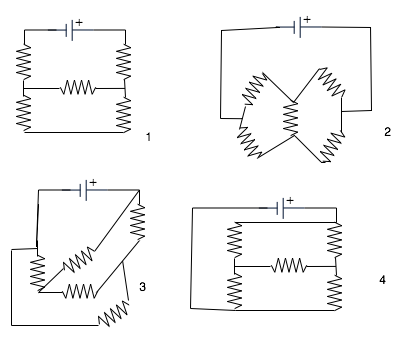 |
Kirchoff's Laws
Almost every circuit can be solved by Kirchoff's First and Second laws
| Kirchoff's Point Law: the algebraic sum of currents into a junction is 0. (algebraic sum means current in is positive, current out is negative)
(What goes in must come out!)
I₁ - I₂ -I₃ = 0
|
 |
| Kirchoff's Loop Law: the sum of P.D.'s round any circuit is zero (What goes up must come down!
|
 |
To continue the fluid analogy: if we think of the wire as a pipe, and charge as a liquid
- The current is the rate of flow of the liquid
- The potential difference is the pressure that keeps the liquid moving
- The resistance is the "narrowness" of the pipe
- This makes a number of points almost obvious.
e.g. Kirchoff's 1st Law says
that the algebraic sum of currents into a junction is 0
I₁ - I₂ -I₃ = 0
(algebraic sum means current in is positive, current out is negative) but
this is almost obvious if we think of the charge as a liquid: what flows in
must flow out
|
 |
To use this, must draw a loop round the circuit, and proceed round the circuit until you get back where you started. Count
- +Ɛ when you go through a battery from negative to positive,
- -IR when you go through a resistor in the direction of the current.
Power in circuits:
To move a charge Q round a circuit, we must do work QV. In a time δt, a charge Q = I δt will flow. Hence Power = W. D. /sec
= V I δt  = VI = I²R = V²
     δt                R
(where the last two follow from Ohm's law)
A wire 300 m long is connected across a 120 V supply. If the wire is cut in half, how do the power consumption change>?
- It is doubled
- It stays the same
- It is halved
More interesting are circuits with several resistors, which can be either
| in series |
 |
| or in parallel
|
 |
| or both |
 |
There is a trick for solving these circuits:
- resistors in series can be replaced by an equivalent resistor. The same current must flow through each one,
- so that
V = IR₁+IR₂+IR₃
 =IR
-
so that
R = R₁+R₂+R₃
|
 |
-
i.e. for resistors in series, the total resistance is the sum of the individual ones
For resistors in parallel
- Now there must be the same voltage across each one:
V = I₁R₁ = I₂R₂ = I₃R₃
=IR
- Hence
I₁=V/R₁, I₂=V/R₂, I₃=V/R₃
and I = V/R but
I = I₁+ I₂+ I₃
- so
1 = 1 + 1 + 1
R   R₁  R₂  R₃
|
 |
- i.e. for resistors in parallel, add the reciprocals and take the reciprocal.
- Why is this reasonable? To extend the fluid analogy for electricity, we can think of the resistors as pipes, and the battery as a pump, which provides pressure to keep the fluid flowing. If we have several pipes one after another, it is harder to pump the fluid through them, so the total resistance to flow would be larger. If we have several in parallel, it is like one pipe with a bigger X-sect, so it is easier for the fluid to flow.
As an example: 
If the battery voltage is 9 V, what is the total current?
what is the power consumed in the 3Ω resistor?
Are Xmas-tree lights wired
- In series, so that you get as big a resistance as possible?
- In parallel, so that the resistance can be as low as possible?
- In series, to make sure that the same current flows through each one?
- In parallel, so that is one dies, the rest keep going?
A more subtle example:
| if we have an infinite "ladder" of 1Ω resistors, what is the total resistance?
|
 |
- We can replace this by
Capacitors
This has the solution
Q(t)=VC(1-e-t/RC)
which looks like
|
 . .
|
- Note that
- at t = 0, Q = 0,
- at t = ∞ Q = VC.
- RC is known as the "time-constant"
e.g. if a circuit has R =1000 Ω and C = 100 μF, what is the time constant T = RC?
How long does it take to charge the capacitor to 1/2 its final value?
Complex Circuits
A warning: many circuits cannot be reduced to series or parallel:
| e.g. the Wheatstone Bridge. You cannot say whether R is in parallel or in series with any of the other resistors. |
 |
Sometimes we can get immediate results without really solving the circuit completely:
| e.g all the resistances in the attached circuit are 15Ω. What is the current through the indicated one? |
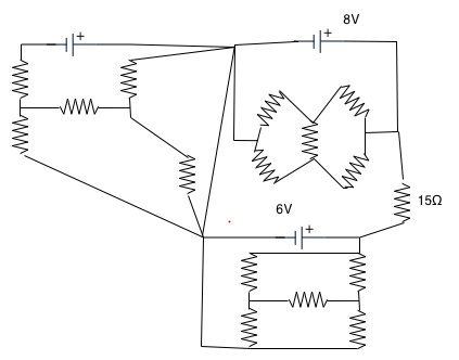 |
| Easy if you pick out the loop indicated! | 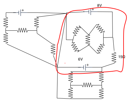 |
Kirchoff's Law
To solve this kind of circuit., we really need to use
Kirchoff's Law for Complex Circuits
This is more complicated:
-
Don't Panic!
-
| As an example of K's laws for a more complex circuit, consider two batteries with voltage
and 3 resistances
- R₁ = 5 Ω
- R₂ = 10 Ω
- R₃ = 15 Ω
and we want to find the current through R₃ . |
 |
Note you cannot use parallel-series arguments.
-
|
Put in currents in each part of the circuit: |
 |
remember what flows in must flow out, which gives
I₁-I₂-I₃=0
|
 |
Then put in as many loops as you need:
- e.g.
V₂+I₂R₂-I₃R₁=0 [A] |
 |
V₁-I₃R₁-I₁R₃=0 [B]
|
 |
V₁-I₂R₂-I₁R₃-V₂ =0 [C]
- Rearrange these:
I₂R₂-(I₁-I₂)R₁ =-V₂
(I₁-I₂)R₁+I₁R₃ =V₁
- so
-I₁R₁+I₂(R₂+R₁) =-V₂
I₁(R₁+R₃)-I₂R₁ =V₁
- (for once you are allowed to put numbers in before the end of the calculation!)
-5I₁+15 I₂ =-5
20 I₁-5 I₂ =7
- You should get I₁=0.29A.
Batteries in Reality
We have treated batteries as just a source of EMF: why don't we talk about the voltage of the battery?
| All of them have an internal resistance, which must be taken into account. Ɛ is the voltage that would be measured only if no current was flowing. e.g.
|
 |
- Suppose Ɛ = 12 V and r = 1 Ω: what would the current be if it was connected across a 5 Ω load?
- What would the voltage measured across the battery terminals be in that case?
| What external resistance R would we need to use to get the nominal voltage if the internal resistance is r?
- ∞
- r
- 0
|
|
Batteries in series and parallel:
| we can usually regard this as a series-parallel problem. |
 |
It is important when we are trying to charge a battery, when we must have the current flow from+to -: e.g.
Suppose Ɛ₁ = 20 V,Ɛ₂ = 12V and the resistances are all 1Ω, what is the current?
- Batteries are usually rated in A-hrs:
- e.g. a battery rated at 90 A-hrs would supply 90 A for 1 hr, or 1 A for 90 hrs
- (but don't count on it in an Ottawa winter!)
Measurement of Current and Voltage
All devices actually measure a very small current: galvanometer consists of coil suspended in magnetic field: torque corresponds to current, measuring (say) 1 mA. How do we measure large currents or large voltages with such a device?
- e.g.: an ammeter measuring a current of 20 A has to be constructed from a galvanometer, with a max current of 10 mA and an internal resistance of 100Ω. What should the "shunt resistance" R be?
- e.g. a voltmeter is to measure a voltage of 12 V has to be constructed from the same galvo. What should the series resistance be?
-
Combinations of capacitors
- Practical circuits often combine different elements, such as resistors, capacitors and inductances (and "active" elements like transistors etc). Hence we need to know how to combine them. e.g.
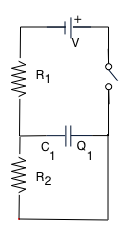
| SImplest possible is just a capacitor and battery (in paractice always have an resistance). Can assume that battery just applies constant voltage. |
 |
-
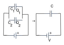
In parallel: we want to replace 2 capacitors by a single equivalent one: in this case that must have the same voltage across each one, so
Q₁ = V C₁, Q₂ =V C₂, Q = VC but Q₁ + Q₂ = Q
-
so that
C = C₁ + C₂
- this is almost obvious, if we think of C₁ and C₂ as being part of a larger cap. C.
|
 |
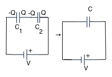
In series: in this case the central part is isolated and neutral, so charges must be +Q and -Q as shown. Hence
V = V₁ + V₂ = Q = Q  + Q
              C   C₁   C₂
so that
1 = 1  + 1
C   C₁   C₂
|
 |
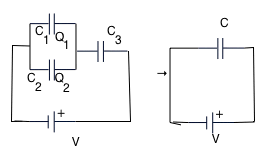
| e.g
suppose C₁ = 1 μf,C₂ = 2 μf, C₃ = 12 μf, what is the equivalent capacitance of the circuit? |
 |
Currents lead us on to magnetism