
Advanced Technology Solar Telescope (ATST)
|
Objectives: by the end of this you will be able to
|
|
Advanced Technology Solar Telescope (ATST) |
|
| Off a plane surface : Note direction of propagation gets reversed |  . . |
| If we have an extended object, this will create an image. To find out where the image appears to be, extend the line of sight |  |
| To get the sensation of depth, we need binocular vision |  |
| This is based on angle of incidence = angle of reflection | θ₁ = θ₂ |

|
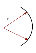
| E.g. concave mirrors: different bits of the mirror reflect the wave according to the local angle of incidence |  |
| The effect in this case is to focus the wave |  |
| This is reversible: if we have a source at the centre of a curved mirror, we have a plane wave (well almost) coming out |  |
| Convex mirrors cause waves to diverge
Note that these behave as if there is a focus behind the mirror |

|
Velocity in medium 1 =  v₁ = n₂
Velocity in medium 2    v₂   n₁
Note that the refracted wave is bent since the wavelength is decreased.
This gives rise to Snell's law, when the wave hits the interface at an angle
n₁ sin(θ₁) = n₂ sin(θ₂) |
 |
We have already seen how a single surface refracts. All optical instruments have at least 2 surfaces.
A prism deflects light via two successive refractions
sin(θ₁) = n sin(θ₂)etc |
 |
| Light can go from a dense medium to a less dense one at an "impossible" angle: e.g in crown glass, what would happen to a ray whose angle of incidence was θ = 60o? |  |
| A prism can be used to show total internal reflection |  |

How does a lens form images?.
| We can build up a lens from a series of prisms |  |
| We could add a 2nd. prism, to deviate light more, so that two rays go through the same place |  |


There are a variety of lens, but essentially they are
|
 |
| The most important quantity for a lens is the focal length f: i.e. how far from the lens do parallel rays get focussed. |  |
| Concave lenses cause light to diverge, but the rays can be traced back to an (imaginary) focus. |  |
| Images are formed as either real or virtual: only a convex lens (positive focal length) can form a real image |  |
| This is the derivation of the "thin-lens" formula. We can use this to find the relation between the distance to the object, the image and the focal length | |
| The magnification
\color{red}{
M = \frac{{{\rm{image height}}}}{{{\rm{object height}}}} = \frac{{h_i }}{{h_0 }}}
(M can be < 1) |
 |
| We have two sets of similar triangles:
\color{red}{
\left| {\frac{{h_i }}{{h_0 }}} \right| = \frac{{d_i }}{{d_0 }} = \frac{{d_i - f}}{f}}
so
\color{red}{
\frac{{d_i - f}}{f} = \frac{{d_i }}{{d_0 }} \Rightarrow \frac{1}{f} = \frac{1}{{d_0 }} + \frac{1}{{d_i }}}
|

|
     1      =    1      +      1
focal length object dist.   image dist.
\color{red}{
\frac{1}{f} = \left( {n - 1} \right)\left( {\frac{1}{{R_1 }} + \frac{1}{{R_2 }}} \right)}
|
 |
f = R/2 because if you place a source at the centre the light must be reflected back there. 1 = 1 + 1 f R R |
 |
| e.g. a spoon
|
 |
| What happens if you look at the front of the spoon? Image is real and inverted | 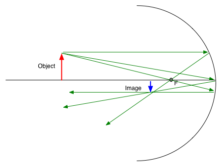 |
| Image is virtual and upright. Note we are drawing dotted lines to extend the rays through the foci. |  |
